🧩 Chapter 1 — Python Baseline Model
AITL Architecture: PID × FSM × LLM
This chapter provides the foundational behavioral model used throughout the AITL Silicon Pathway.
The Python implementation here defines the golden reference used for RTL, OpenLane, GDSII, and SPICE stages.
🔗 Official Links
| Language | GitHub Pages 🌐 | GitHub 💻 |
|---|---|---|
| 🇺🇸 English |
⚠ Diagram Rendering Notice
The system pathway diagram above is written in Mermaid.
Due to current limitations of GitHub Pages, Mermaid diagrams are not rendered on this site.Please refer to the GitHub repository view (linked above) to see the diagram correctly rendered.
📘 What You Will Learn
- Structure of the AITL 3-Layer Architecture
- Behavior of PID controller, FSM, and supervisory LLM logic
- How Python simulation becomes hardware specifications
- Step response & fault response simulation
- How Chapter 1 connects to ASIC implementation
📂 Chapter 1 Contents
| File | Description |
|---|---|
| README.md | Folder-level overview & usage guide |
| overview.md | Conceptual explanation of control architecture |
| python_model.md | Detailed explanation of the PID/FSM/Controller code |
| fsm.md | Canonical AITL FSM specification (used for RTL) |
| api.md | API reference for the Python model |
| getting_started.md | Installation & execution guide |
🗂 Directory Map
chapter1_python_model/
├─ example/                # Jupyter notebooks
├─ plots/                  # Generated plots
├─ sim/                    # Simulation scripts
├─ src/                    # PID / FSM / Controller code
├─ tests/                  # Unit tests
├─ main.py                 # Entry example
└─ requirements.txt        # Dependencies
🎯 Role of Chapter 1 in the Full Silicon Pathway
This chapter is the starting point of the end-to-end hardware education pipeline:
Python → Verilog (RTL) → OpenLane → GDSII → Magic RC Extraction → SPICE
✔ Behavioral correctness is established here
All downstream steps rely on the Python model as the reference.
✔ FSM rules defined here become RTL (Chapter 2)
✔ Controller timing and transitions influence ASIC design (Ch.3–5)
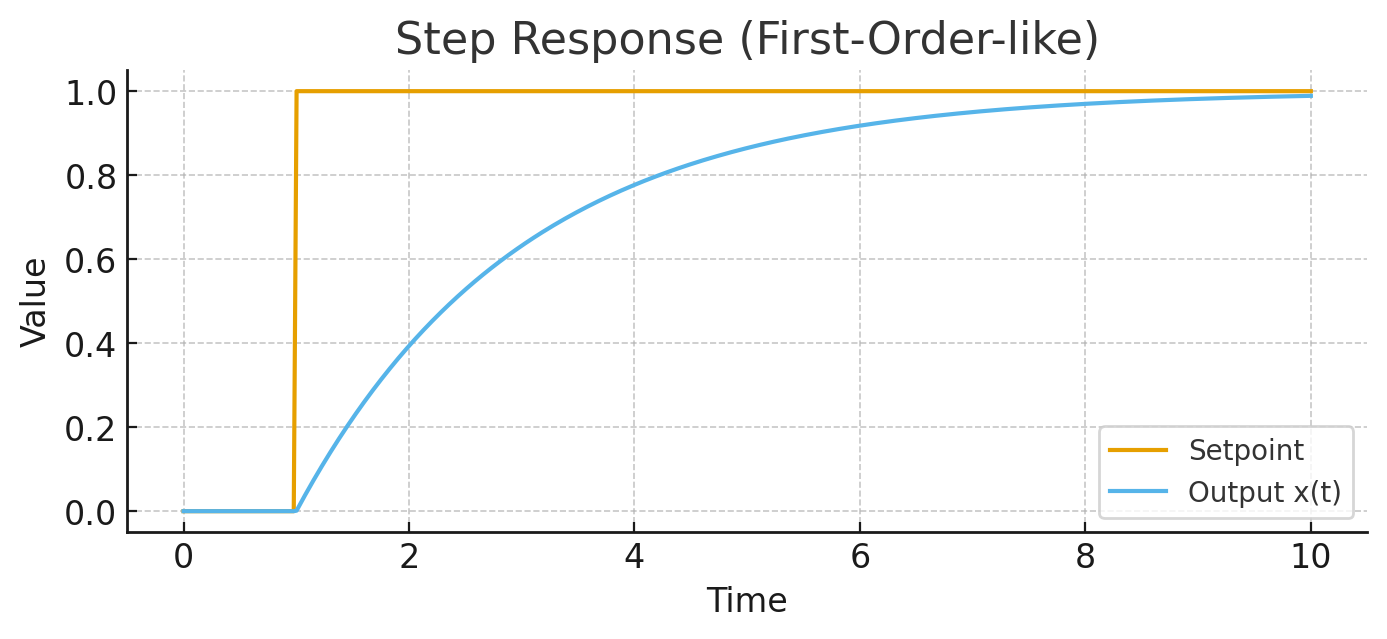
🧪 Simulations
Step Response
Produces controller output, PID action, and FSM transitions.
Fault Scenario
Simulates transient fault injection and automated recovery.
Images are stored here:
docs/chapter1/images/
🖼 Key Diagrams (GitHub Pages absolute paths)
FSM Overview
flowchart TD
    PY[Python Baseline Model]
    SPEC[FSM Specification]
    RTL[Verilog RTL]
    OL[OpenLane Flow]
    GDS[GDSII Layout]
    EXT[RC Extraction]
    SPICE[SPICE Simulation]

    PY --> SPEC
    SPEC --> RTL
    RTL --> OL
    OL --> GDS
    GDS --> EXT
    EXT --> SPICE
Controller Data Flow
flowchart TD
    R[Reference]
    E[Error]
    PID[PID Controller]
    FSM[FSM Supervisor]
    PLANT[Plant]
    Y[Output]
    LLM[LLM Meta Control]

    R --> E
    Y --> E
    E --> PID
    PID --> PLANT
    PLANT --> Y

    FSM --> PID
    FSM --> PLANT

    LLM -. tuning .-> PID
    LLM -. policy .-> FSM
Step Response Simulation
🔗 Continue Reading
👉 Next: overview.md
👉 or jump to python_model.md