【Mechanical Design】🛠️ 04. Introducing Code-Based Design Without Abandoning Part Design — A Practical Solution in FreeCAD
topics: [“mechanical design”, “cad”, “freecad”, “python”, “design philosophy”]
🧭 Introduction
In the previous articles, we have seen that:
- Design can be described as code
- FreeCAD can actually generate geometry from that code
However, most engineers working in real projects will likely think:
“But in practice, we use Part Design, right?”
This article answers that question directly.
Do not abandon Part Design.
Move only the design conditions to code.
This is the practical, non-fragile solution
for introducing code-based design in real workflows.
🎯 What We Will Do in This Article
This article focuses on clarifying
the division of responsibilities in design.
- Define design conditions (dimensions, decisions) in code
- Reflect them into a FreeCAD Spreadsheet
- Continue using Part Design (Sketch / Pad) as usual in the GUI
- Complete dimension changes only via the Spreadsheet
This is not about drawing everything with code.
🧩 Overview of the Final Structure
First, let’s look at the final structure.
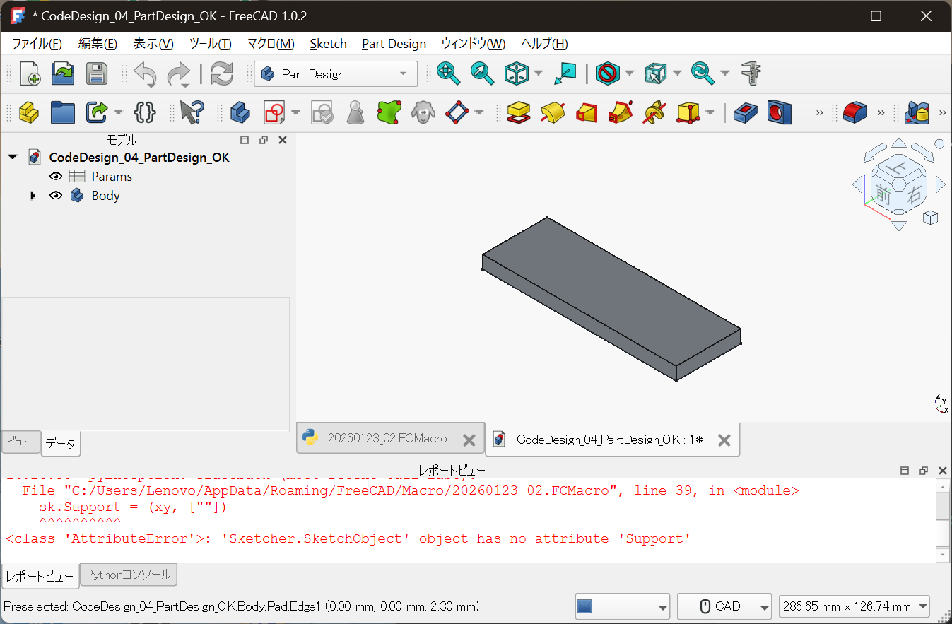
Params: Design conditions (upstream)Body: Geometry created with Part Design (downstream)
The core of the design lives in Params,
and the geometry is generated as a result.
📊 Centralizing Design Conditions in a Spreadsheet
The core of the design is not:
- Sketches
- Pads
It is the Spreadsheet.
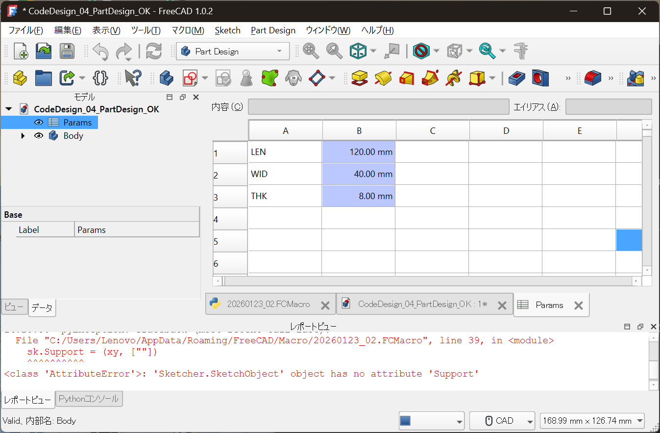
LEN = 120.00 mm
WID = 40.00 mm
THK = 8.00 mm
- Meaningful variable names
- Values with units
- Changing only this location modifies the design
Creating this state is the goal.
🧪 The Role of Code Is Only “Preparation”
In this configuration,
the role of code is intentionally minimal.
- Create the Spreadsheet
- Write design parameters into it
- Link Sketch and Pad constraints via expressions
The geometry itself is not drawn by code at all.
🧠 Why This Structure Is Realistic
Part Design Is Not Rejected
- Constraint-based sketching
- Feature history
- Compatibility with drawings and downstream processes
These remain essential in real-world design.
But Design Conditions Are Not Buried in the GUI
At the same time:
- Why is this dimension chosen?
- What changes if this value changes?
- What was the design decision?
If these are embedded inside sketches,
they become hard to trace later.
Design conditions must live
in a place that can be read independently.
🧱 Clear Separation of Responsibilities
The essence of this approach is not
“turn everything into code.”
| Responsibility | Owner |
|---|---|
| Design conditions / decisions | Code / Spreadsheet |
| Geometry creation | Part Design (GUI) |
| Visual confirmation | CAD view |
Do not put everything in code.
Do not leave everything to the GUI.
This division is why the workflow remains robust.
🔁 Daily Workflow in Practice
Daily operation is very simple.
- Open
Params(Spreadsheet) - Change numerical values
- Recompute
- Geometry updates automatically
There is no need to touch
Sketches or Pads.
🧭 Difference from Article 03
- 03:
Geometry generated purely by code (proof of concept) - 04:
Clear role separation between code and GUI (practical adoption)
Article 04 is where
the method becomes usable in real projects.
🏁 Conclusion
Code-based design is not meant
to replace GUI CAD.
It is a method to preserve design conditions
and design decisions in a reusable form.
Continue using Part Design,
and move only the upstream logic into code.
This is the realistic entry point
for Full Code Mechanical Design.
In the next article, we will discuss:
How to manage this design with Git
— diffs, redesigns, and handover.
📎 Notes
This article focuses on understanding
the separation of responsibilities between
design conditions and geometry generation.
For detailed specifications of FreeCAD’s Spreadsheet
and Part Design workbench,
please refer to the official documentation.
This article does not recommend or restrict
the use of any specific product or license.