【Hardware】 🧱 04. aitl-physical-reference v3
Physical Control Insertion Reference — The Only Point You Are Allowed to Touch
This article explains aitl-physical-control v3.
It is a direct continuation of v2.
📌 Conclusion First
v3 is not the version where control begins.
It is the version that defines how far control may be inserted without breaking physics.
In v2, we froze:
- Copper geometry
- Current paths
- Board outline
- The meaning of V–I relationships
In v3, none of these are changed.
Instead, exactly one point is defined where interaction is allowed.
❓ What Was the Limit of v2?
v2 defined a complete physical loop:
VCC → R → LED → GND
- Measurable
- Unbreakable
- Manufacturable
- But entirely immutable
This is correct.
But it leaves one essential question unanswered:
“Where does control actually enter the physical world?”
v3 exists solely to answer this question.
🧠 Design Philosophy of v3
v3 follows a single rule:
The physical loop frozen in v2 must remain unchanged.
On top of that rule, v3 allows:
- Physical interaction
- Continuous influence
- Non-destructive modification
At exactly one point.
🔁 Version Summary (v0 → v3)
| Version | Role |
|---|---|
| v0 | A collection of passive physical components |
| v1 | Semantic definition between logic and physics |
| v2 | Frozen executable physical loop |
| v3 | Definition of the minimal control insertion point |
v3 does not replace v2.
It explicitly marks where touching is allowed on top of v2.
🖼 v3 Figures (Embedded)
Fig.10 — v3 Schematic (Minimal Control Insertion)
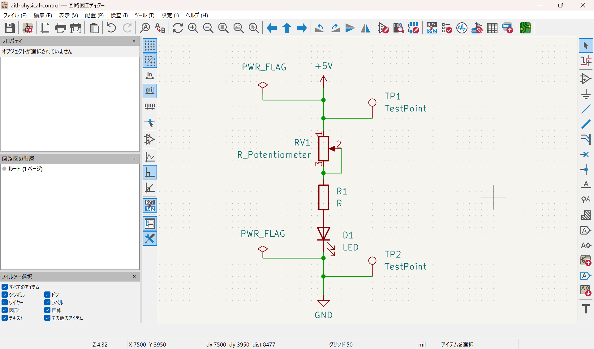
- Identical physical loop to v2
- Only one addition: a single variable resistor (RV)
- Wiper is physically shorted (semantic fixation)
Fig.11 — v3 PCB Layout (DRC-clean)
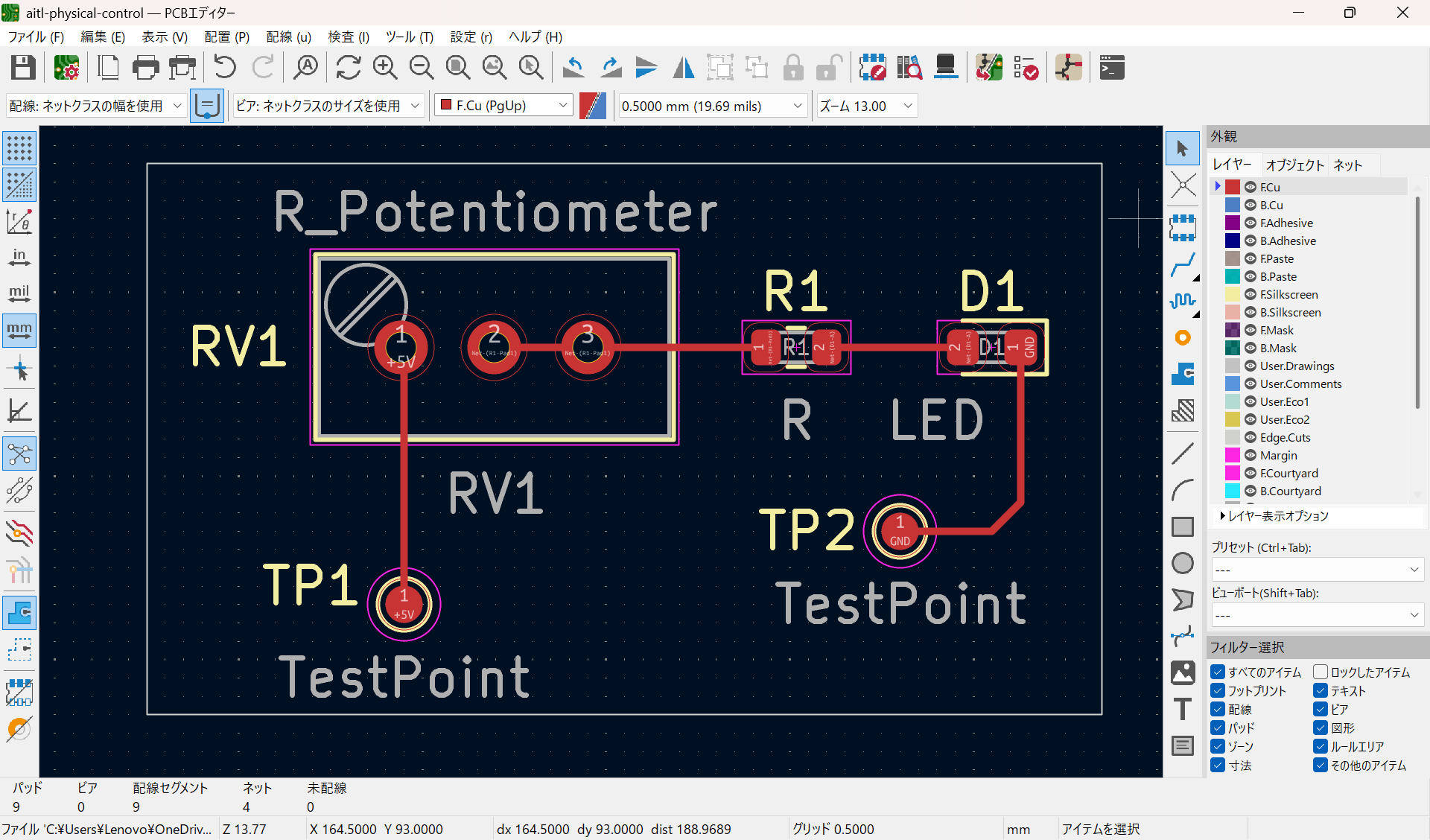
- Loop routing is identical to v2
- RV is inserted in series with the loop
- Observation points (+5V / GND) preserved
Fig.12 — v3 3D View (Controllable Reality)
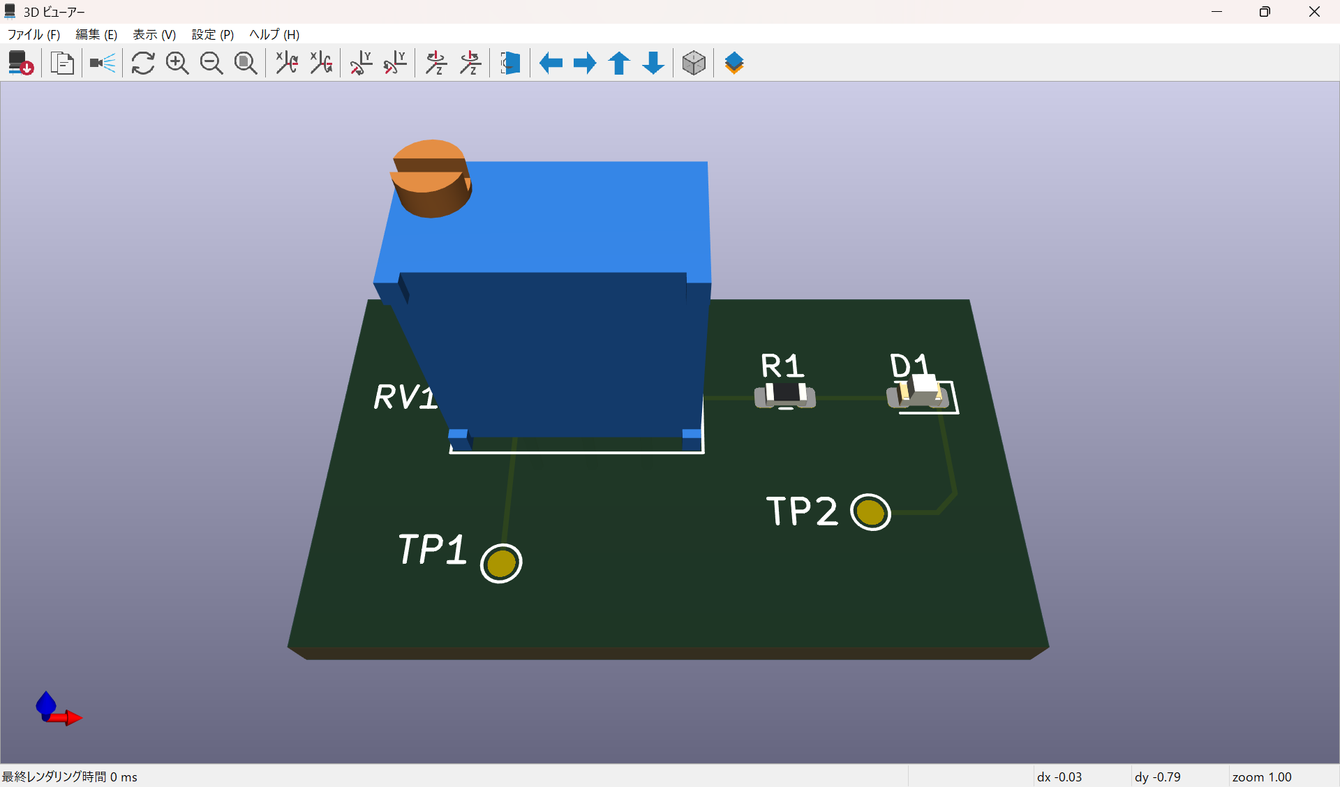
- Control element exists as a physical object
- It can be turned, but not abused
- Physics still enforces boundaries
📦 What v3 Includes (ONLY)
- 🔁 The same physical loop as v2
- 🧮 A continuous control element (variable resistor)
- 📍 +5V / GND observation points
- 📐 Fixed board outline
🚫 What v3 Never Includes (NEVER)
- ❌ MCU
- ❌ GPIO
- ❌ PWM
- ❌ Feedback control
- ❌ Judgment or state transitions
v3 exists before control algorithms begin.
🎛 Why a Variable Resistor?
A variable resistor is:
- Not discrete
- Not time-based
- Not semantic
It is a pure continuous physical quantity.
The question v3 asks is:
“How far may control move a physical quantity?”
The smallest possible answer is RV.
🧱 Position of v3 Within AITL
| Layer | Role |
|---|---|
| LLM / AI | Meaning and redesign |
| FSM | State transitions |
| PID | Continuous control |
| v3 | Physically allowable control insertion point |
| v2 | Frozen physical facts |
| Physics | Heat, light, current |
v3 is the entry point of control,
but physics still holds authority.
🔒 Stability Rule (v3)
The physical loop frozen in v2 is immutable.
- Control laws → higher layers
- Physical changes → new reference (v4 or later)
v3 itself is an experimental reference, not an evolution point.
🧾 Summary
- v2 defined what must never be touched
- v3 defines the only point that may be touched
- Control exists only by respecting physics
➡ Where to Go Next
- v3 + PID: introduction of continuous control
- v3 + FSM: state-dependent control switching
- v3 + MCU: separation of meaning and physics
These belong outside v3, not inside it.
🔗 References
-
Physical Reference (v0–v2)
https://samizo-aitl.github.io/aitl-physical-reference/ -
Physical Control (v3, KiCad)
https://github.com/Samizo-AITL/aitl-physical-reference/tree/main/hardware/kicad/aitl-physical-control