【Hardware】 🧱 03. aitl-physical-reference v2
Physical Loop Reference — Freezing Copper and Current Before Control
This article explains aitl-physical-reference v2.
Let us start with the conclusion.
v2 is not a version that increases what can be controlled.
It is a version that freezes what must not be controlled — copper, current, and outline.
❓ Why v2 Is Necessary
When we discuss control, FSM, PID, or AI,
we unconsciously assume the following:
- Voltage is available
- Current flows
- LEDs light up
- GND is actually GND
However, these are not logical assumptions.
They are physical facts.
v2 exists to answer only one question:
“If we freeze a complete voltage–current loop without introducing any control at all, what remains?”
🔁 Differences Between v0 / v1 / v2
| Version | Role |
|---|---|
| v0 | A collection of passive physical components |
| v1 | Semantic definition between logic and physics |
| v2 | Executable physical loop (DRC-clean) |
| v3 | Insertion of control (FSM / PID) |
Where v1 defined:
“What does it mean for this pin to be High?”
v2 freezes:
“What copper geometry makes that meaning physically valid?”
🖼 v2 Figures (Embedded)
Fig.07 — v2 Schematic (Executable Physical Loop)
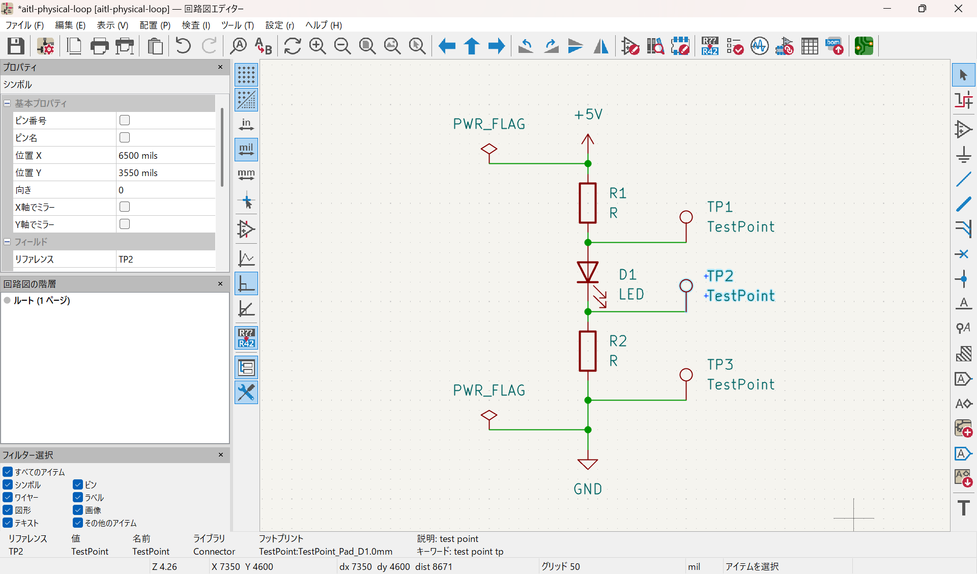
- A single, closed V–I loop
- Only current limiting (R) and physical output (LED)
- Test points that do not destroy the loop
Fig.08 — v2 PCB Layout (DRC-clean, Manufacturable)
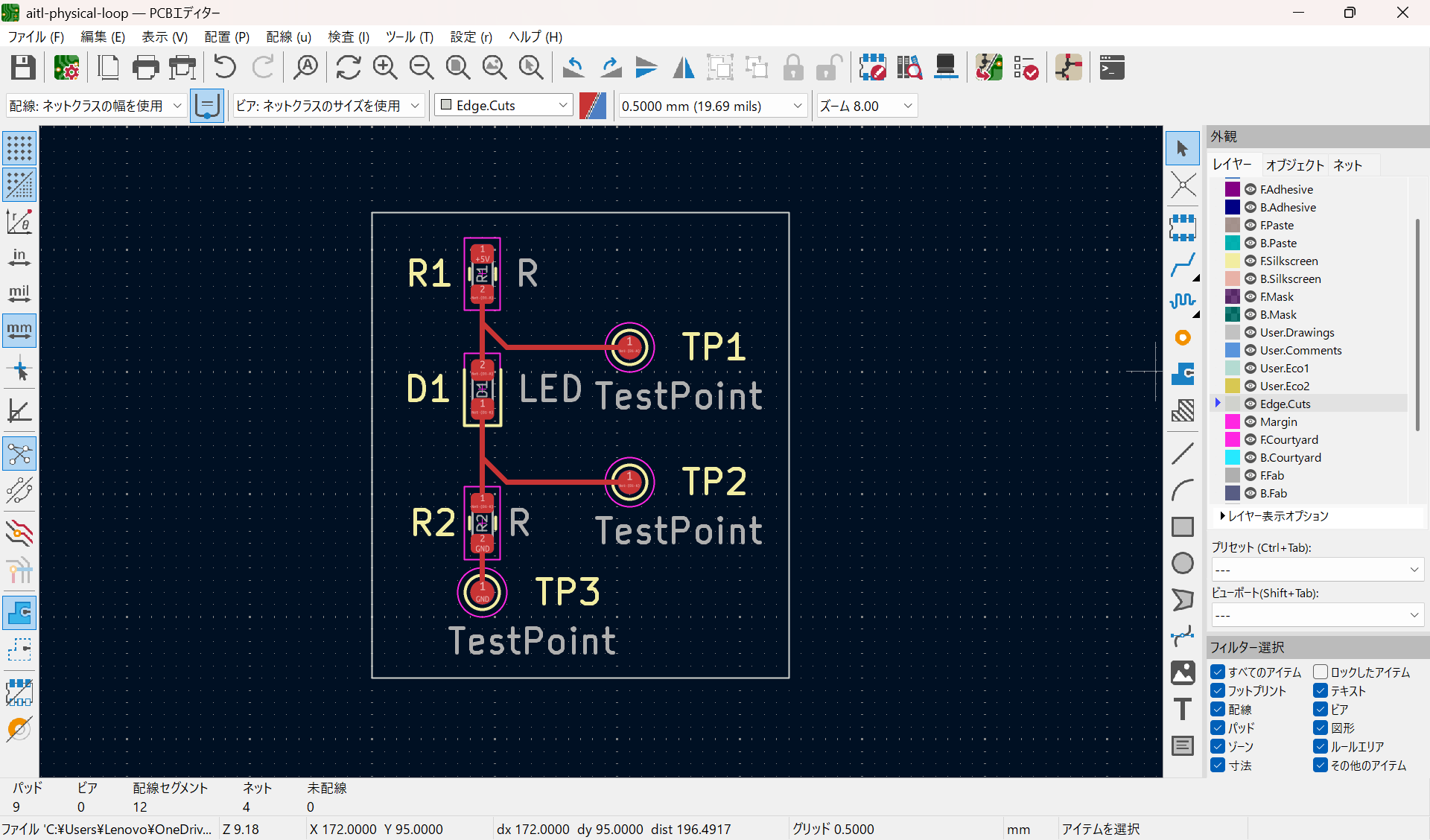
- Explicit Edge.Cuts defined
- Zero unrouted nets, no arbitrary copper zones
- Physical constraints directly reflected in copper
Fig.09 — v2 3D View (Embodied Reality)
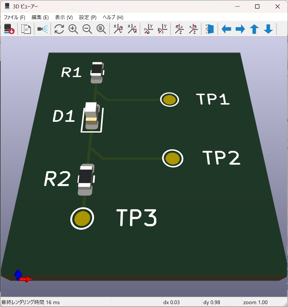
- Real height and real clearance
- Embodied boundaries, including probe accessibility
📏 Design Principles of v2 (Strict)
In v2, what is not allowed matters more than what is allowed.
Included (ONLY)
- 📐 Explicit Edge.Cuts (board outline)
- 🔁 Single, closed current loop
- 🧮 Current limiting element (R)
- 💡 Physical output (LED)
- 📍 Test points that do not break the loop
Excluded (NEVER)
- ❌ MCU
- ❌ GPIO semantics
- ❌ Feedback
- ❌ Timing
- ❌ Intelligence or judgment
v2 is designed to stop immediately before control begins.
🔄 What Is a Physical Loop?
What v2 freezes is the following inseparable V–I loop:
VCC → R → LED → R → GND
This is not a logical structure.
It is a physical fact.
- Where voltage drops
- Where heat is generated
- Whether the loop survives measurement
These must never be decided by control logic.
👁 Observability
Test points in v2 satisfy all of the following:
- They do not cut the loop
- They do not alter the current path
- Measurement does not change the meaning
“Measurable, but untouchable.”
This is the observability rule of v2.
🧱 Position of v2 Within AITL
| Layer | Role |
|---|---|
| LLM / AI | Meaning and redesign |
| FSM | State transitions |
| PID | Continuous control |
| v2 | Immutable physical facts |
| Physics | Heat, light, current |
v2 is the frozen lowest layer.
🔒 Stability Rule (v2)
Current paths, V–I meaning, and board outline are immutable.
If changes are required:
- v2.x: documentation and diagrams only
- v3: a new reference that includes control
🧾 Summary
- v2 does not make the system more convenient
- v2 exists to protect control
- Freeze copper before adding control
🔗 References
-
Project Top
https://samizo-aitl.github.io/aitl-physical-reference/ -
Hardware (KiCad)
https://github.com/Samizo-AITL/aitl-physical-reference/tree/main/hardware/kicad