🧭 Overview
V–I Control ASIC on SKY130
This project demonstrates how a Voltage–Current (V–I) based control system can be implemented as a fully digital ASIC, using OpenLane and SkyWater SKY130.
The focus is on clarity, determinism, and educational value.
🎯 What This Project Is
This repository is:
- 📘 A step-by-step educational guide
- 🧩 A practical control ASIC reference design
- 🛠 A complete RTL-to-GDS example using open-source tools
You will see how:
Control theory becomes fixed-point math,
fixed-point math becomes RTL,
and RTL becomes silicon.
❌ What This Project Is NOT
To keep the scope clear, this project is not:
- A high-performance AI accelerator
- A mixed-signal SoC with on-chip ADC/DAC
- A vendor-specific MCU example
All analog functions (ADC, DAC, current sensing) are intentionally kept off-chip.
⚡ Core Idea: V–I Based Digital Control
The control system operates on two physical quantities:
- Voltage (V)
- Current (I)
These are sampled by external ADCs and provided to the ASIC as digital fixed-point values:
- $V[n]$ : voltage sample
- $I[n]$ : current sample
The ASIC computes a control output:
- $u[n]$ : control command → PWM duty or timing
🧩 Target Architecture (Concept)
V[n], I[n]
│
▼
+----------------+
| PID Controller | ← Fixed-point arithmetic
+----------------+
│ u[n]
▼
+----------------+
| FSM Supervisor | ← INIT / RUN / FAULT
+----------------+
│
▼
+----------------+
| PWM Generator | ← Digital pulse output
+----------------+
🧠 RTL-Level Architecture (Actual Implementation)
The following figure shows the top-level RTL behavior of the V–I control system, verified by RTL simulation.
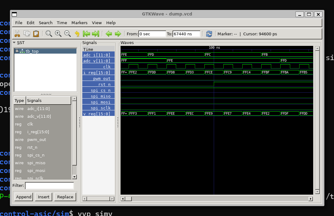
This view reflects the actual integration of:
- Register interface (SPI)
- Fixed-point PID core
- FSM supervisor
- PWM generator
This figure is used here only to illustrate block interaction.
Detailed signal-level verification is provided in Appendix A.
🔁 FSM Supervisor Overview
The control behavior is governed by a hardware finite-state machine (FSM) with explicit operating states.
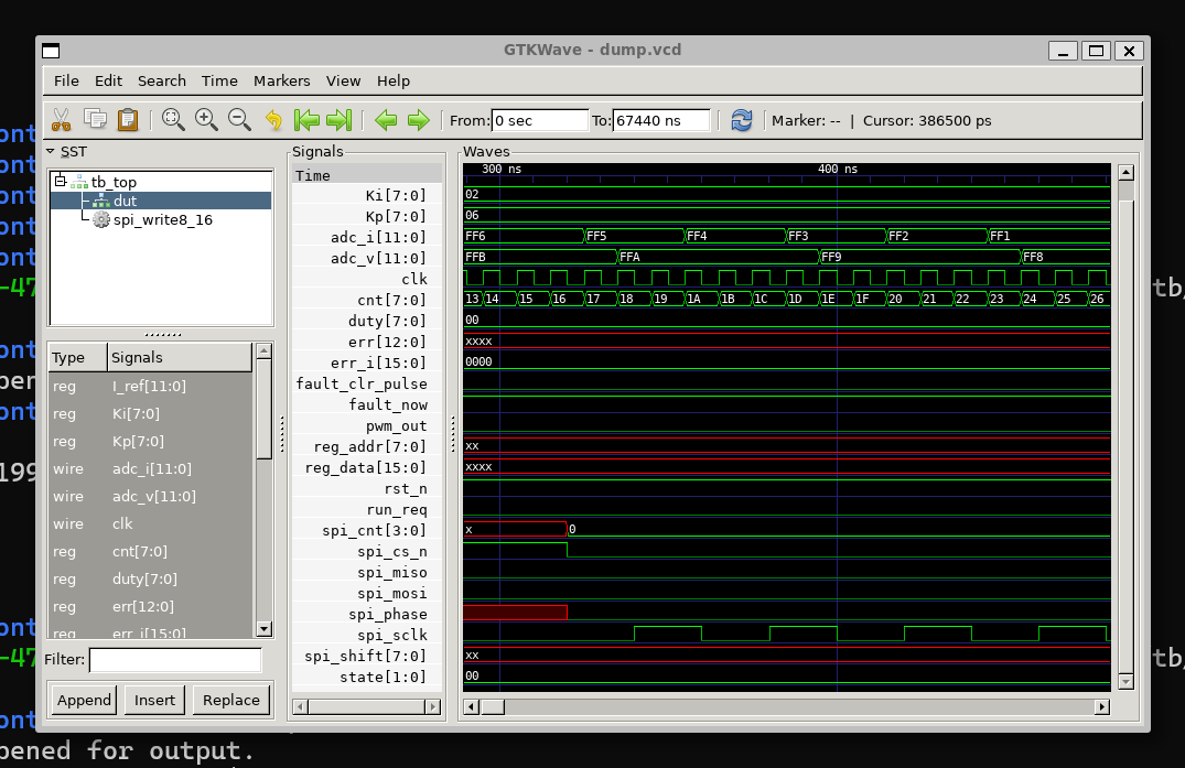
The FSM enforces:
- Safe startup sequencing
- Deterministic RUN behavior
- Immediate FAULT handling
All state transitions are fully synchronous and cycle-accurate.
🧭 FSM State Definition
The FSM explicitly defines the following states:
-
INIT
Reset and parameter loading via SPI -
RUN
Normal closed-loop control operation -
FAULT
Latched error condition requiring explicit clear
Waveform-level FSM verification results are collected in
Appendix A: Figure List.
⏱ Why ASIC-Based Control?
Compared with MCU-based control:
| MCU | ASIC (This Project) |
|---|---|
| Interrupt-driven | Fully synchronous |
| Variable latency | Deterministic latency |
| Software hidden states | Explicit hardware states |
| Difficult timing analysis | Exact cycle count |
For industrial and safety-oriented control, determinism matters.
🛠 Technology Stack
- Process: SkyWater SKY130 (130 nm)
- EDA Flow: OpenLane
- Design Style: Digital-only, single clock
- Language: Verilog HDL
- Arithmetic: Fixed-point
All designs in this repository are compatible with the open-source SKY130 PDK.
📚 Documentation Structure
The documentation is organized as follows:
-
Overview
System concept and architecture -
Control Model
Discrete-time PID control using V–I feedback -
Fixed-Point Design
Q-format selection, scaling, saturation -
RTL PID Core
Cycle-accurate Verilog implementation -
FSM & PWM
Supervision, safety, and pulse generation -
OpenLane Flow
RTL → GDS implementation and layout analysis
Each chapter builds directly on the previous one.
🧠 Educational Philosophy
This project follows three principles:
- Make timing explicit
- Make arithmetic visible
- Make behavior explainable
If you understand every block in this design, you understand the essence of a practical control ASIC.
➡️ Next
Proceed to the control formulation:
The next chapter introduces the discrete-time V–I based PID control model used throughout this design.