04.【FCMD】 Introducing Code-Based Design Without Abandoning Part Design
— A Practical Solution in FreeCAD
tags: Mechanical Design, CAD, FreeCAD, Python
Introduction
In the previous article,
I showed an example of generating geometry using only code in FreeCAD.
However, most practicing mechanical designers will immediately think:
“But in real work, we use Part Design, right?”
This article answers that question head-on.
Do not abandon Part Design.
Move only the design conditions to code.
That is the practical, non-breaking solution
for introducing code-based design in real-world workflows.
What We Will Do
- Define design conditions (dimensions) in code
- Reflect them into a FreeCAD Spreadsheet
- Use Part Design (Sketch / Pad) as usual in the GUI
- Complete all dimension changes only via the Spreadsheet
Final State (Overview First)
Let’s start with the final structure.
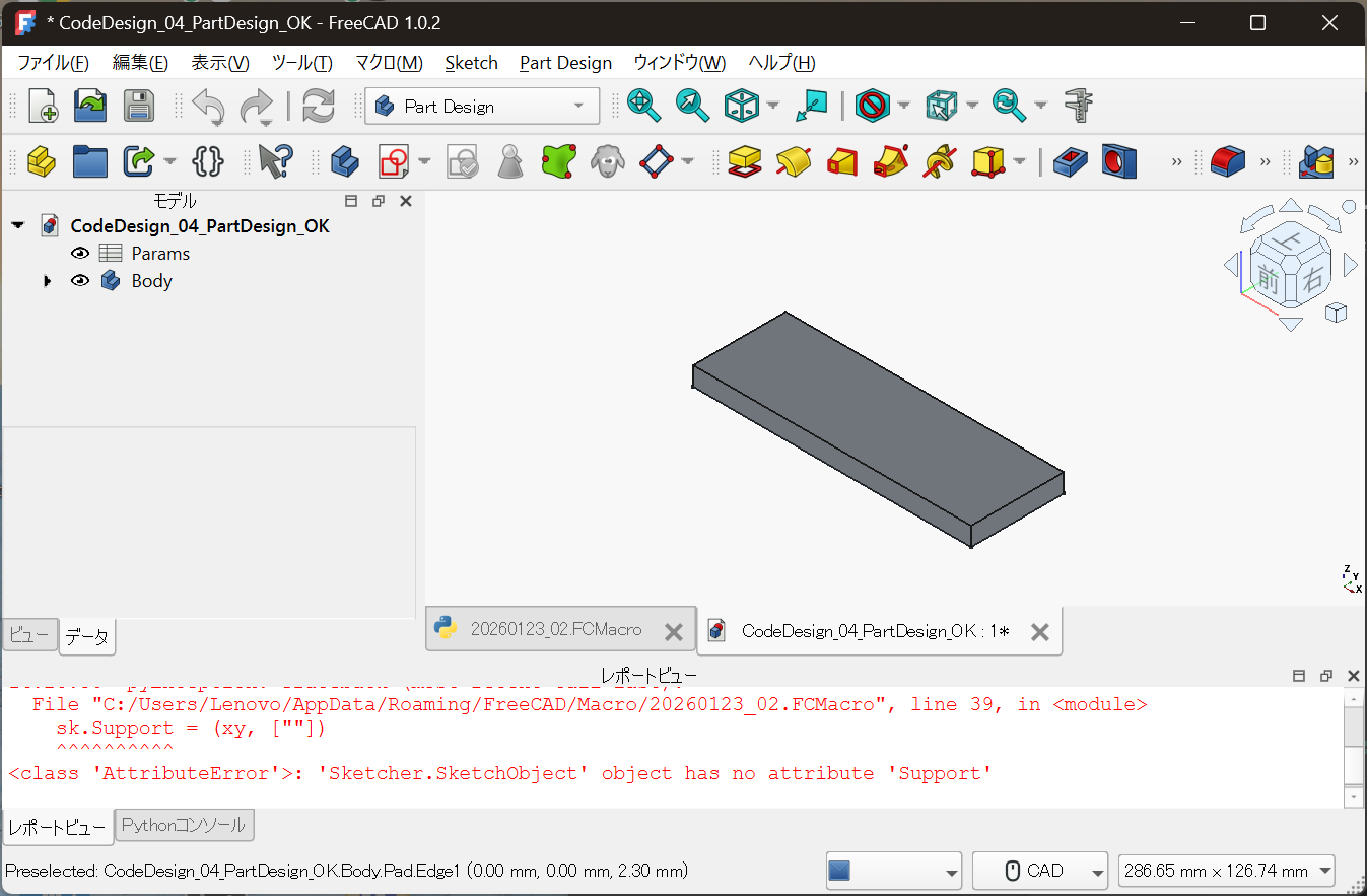
Params: design conditions (upstream)Body: Part Design geometry (downstream)
This separation is the key point of this article.
Centralizing Design Conditions in a Spreadsheet
The core of the design is not:
- Sketches
- Pads
You can see this clearly in the following view.
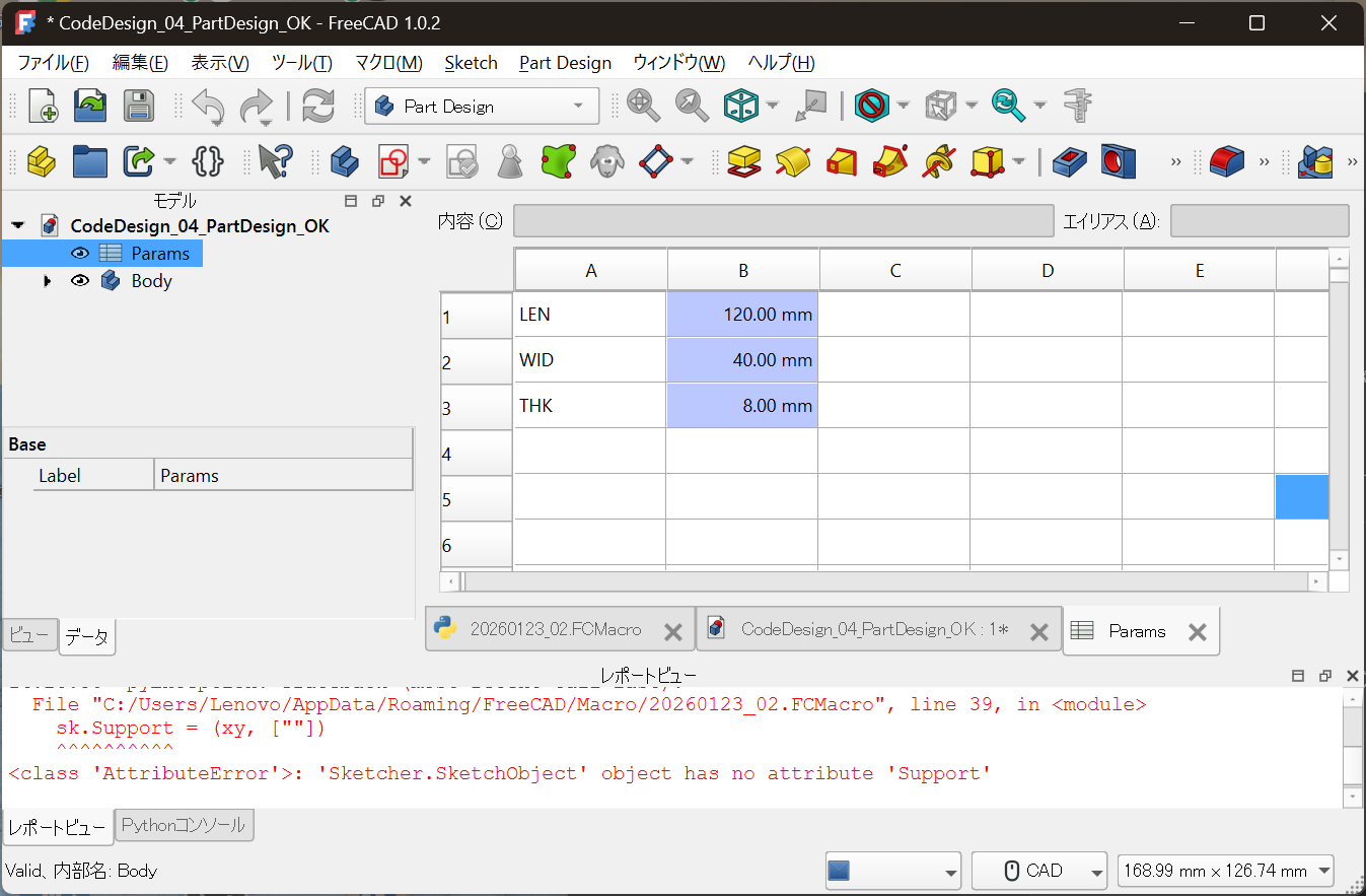
LEN = 120.00 mm
WID = 40.00 mm
THK = 8.00 mm
Key characteristics:
- Meaningful parameter names
- Explicit units
- Changing only this table changes the design
What the Code Actually Does (Minimal Scope)
In this setup, the role of code is intentionally limited:
- Create a Spreadsheet
- Populate design parameters
- Link Part Design constraints and Pad thickness via expressions
The geometry itself is:
Not drawn in code at all.
Why This Structure Is Practical
Part Design Is Not Rejected
Part Design remains valuable because of:
- Sketch constraints
- Feature history
- Compatibility with drawings and downstream processes
These are the reasons Part Design is still used in real workplaces.
But Design Conditions Should Not Be Buried in the GUI
Questions like:
- Why is this dimension chosen?
- Which parameter should be changed?
- What design decision does this represent?
When these are buried inside Sketch constraints,
they become hard to trace later.
Clear Separation of Responsibilities
The essence of this approach is role separation.
| Role | Responsibility |
|---|---|
| Design conditions & decisions | Code / Spreadsheet |
| Geometry generation | Part Design (GUI) |
| Visual verification | CAD view |
Do not code everything.
Do not leave everything to the GUI.
How It Is Used in Practice
- Open the
ParamsSpreadsheet - Change numeric values
- Recompute (Ctrl + R)
- Geometry updates automatically
There is no need to touch the Sketch or Pad.
Difference from Article 03
- 03:
Geometry generated entirely by code (proof of concept) - 04:
Division of labor between code and GUI (practical application)
Article 04 is where the idea becomes
deployable in real design environments.
Conclusion
Code-based design is not about replacing GUI CAD.
It is about preserving design conditions and decisions
in a reusable, traceable form.
Continue using Part Design,
while moving only the upstream logic to code.
This is the most realistic entry point
to Full Code Mechanical Design.
In the next article,
we will move on to managing these designs with Git:
- Diffs
- Redesigns
- Handover and long-term maintenance
Notes
The code shown in this article is provided as an illustrative example
to explain the design methodology.
It is not intended for direct production use or redistribution.
Actual design code and licensing policies are managed here:
- Full Code Mechanical Design
https://samizo-aitl.github.io/full-code-mechanical-design/
Note: FreeCAD’s API may change in the future.
This article focuses on explaining the underlying concept.