🎓 Samizo-AITL Portal
Engineering documentation for semiconductors, MEMS, control, and AI
Physics-based models / PID & FSM real-time control / RTL-to-GDS implementations / PoC
🚀 What This Portal Provides
Samizo-AITL is a technical archive organized around
physics-based assumptions and implementation results.
This portal provides:
- Design documentation with explicit physical and device constraints
- A structured flow from devices → models → control → intelligence
- Design records that document design rationale and constraints, not only implementation steps
- Reusable architecture examples across education, PoC, and practical design
🎯 Intended Audience (Who This Portal Is For)
This portal is intended for engineers and researchers who:
- Start system design from physical models and explicit constraints
- Treat control theory as a core part of the system structure
- Use AI / LLMs as supervisory or analytical layers, not as real-time controllers
- Need cross-domain understanding while preserving physical meaning
🧭 What Is Samizo-AITL?
The Samizo-AITL Portal, created by Shinichi Samizo,
is a technical archive that organizes semiconductor devices, MEMS, and control engineering
using a physics-based design framework.
Systems are described using a single structured flow:
Physics → Structure → Devices → Process → Models → Systems → Control → Intelligence
🗺️ AITL Structure Map (Overall Architecture)
flowchart TB
  %% ===== Physical Layer =====
  subgraph PL["Physical Layer"]
    P["Physical / Devices / MEMS"]
  end

  %% ===== Control Layer =====
  subgraph CL["Control Layer"]
    M["Models"]
    C["Control Theory"]
    R["Real-time PID"]
  end

  %% ===== Supervisory & Design Layer =====
  subgraph SL["Supervisory & Design Layer"]
    S["FSM Supervisor"]
    A["Adaptive Assist (NN / RL, bounded)"]
    I["LLM (Design-time only)"]
  end

  %% ===== Flow =====
  P --> M --> C --> R --> S
  S --> A
  S --> I

  %% ===== Style =====
  style PL fill:#e6f2ff,stroke:#1f4ed8,stroke-width:2px
  style CL fill:#e9ffe6,stroke:#1f8b24,stroke-width:2px
  style SL fill:#fff3e6,stroke:#d86b1f,stroke-width:2px

  style I stroke-dasharray:5 5
AITL (Architecture for Integrated Technology Logic) is a system design architecture
organized around a fixed layer order:
Physical → Control → Intelligence
-
Physical Layer
Physics, devices, and MEMS define
system constraints, operating limits, and sources of uncertainty. -
Control Layer
Control methods based on physical models (e.g., PID)
define stability, response characteristics, and achievable performance. -
Supervisory & Design Layer
- FSM: Manages state evaluation, state transitions, and intervention permissions
- NN / RL: Provides real-time adaptive assistance within FSM-approved bounds
- LLM: Performs analysis, redesign, and design support
offline (non-real-time)
※ LLMs are used only during design-time (non-real-time)
and do not intervene in real-time control loops.
🗂 Directory Overview (Structural Map)
The directory structure itself represents the design philosophy.
Samizo-AITL/
├─ 01_DevEnv/        Environment & Reproducibility
│                   (VSCode / Python / Toolchain)
│
├─ 02_CodeGen/       Implementation & Control
│   ├─ PID           Real-time control (stability, V–I control)
│   ├─ FSM           Supervision, state transitions, mode management
│   ├─ NN_RL         Bounded real-time adaptive assistance
│   └─ LLM           Design supervision & redesign (non-real-time)
│
├─ 03_Docs/          Understanding, Education, Design Philosophy
│   ├─ Edusemi-v4x
│   ├─ EduController
│   └─ Edusemi-Plus
│
└─ 04_Archives/      PoC, history, design assets
🗺 How to Navigate This Portal
-
Architecture
AITL structure and the role of each layer based on physical assumptions -
Physics & Devices
Semiconductor physics, device structures, MEMS, and physical constraints -
Control Architecture
Model-based real-time control (PID) supervised by FSM -
Intelligence (Design-time)
Supervisory logic and LLM-assisted analysis performed offline (non-real-time) -
Proof-of-Concept Implementations
Verification through working systems and reproducible examples
📝 Essays / Design Notes (Zenn / Qiita — English)
🧠 Articles related to design decisions, physical assumptions, and
AITL architecture are managed using
GitHub-hosted Markdown as the Single Source of Truth (SSOT).
📚 Zenn / Qiita are publication channels.
🏛 Authoritative originals are maintained on GitHub Pages.
📚 Zenn (Architecture / Structure — EN)
🏛 Architectural structure and design decisions
🏛 Physics-based engineering assumptions
🏛 AITL structure (PID × FSM × LLM responsibility separation)
📜 Qiita (Introductory / Implementation-oriented — EN)
🔧 Introductory explanations
🔧 Implementation notes and PoCs
🔧 Focused single-topic articles
💠 Semiconductor Physics & Devices
A foundational layer that systematizes semiconductor and device physics from first principles, defining the preconditions for control design.
1️⃣ 📘 Edusemi-v4x
A systematic curriculum covering semiconductor devices and processes:
- Device structures and operating physics
- Process integration flows
- Compact models and PDK concepts
- Circuit-level fundamentals
- SystemDK-based physical constraints
(thermal, stress, SI/PI, EMI)
🔹 Special Chapter: SystemDK (System Design Kit)
A special chapter that builds upon physics-based device and circuit knowledge and extends it into
implementation and system-level integration design, including SI / PI / thermal / mechanical stress / EMI considerations.
- Organizes system-level constraints that cannot be resolved at the device level alone, starting from physical principles
- Provides a unified design perspective spanning SoC, chiplet, package, and board
- Usable not only as educational material, but also as a practical design thinking framework for real implementations
👉 Positioned as a bridge from “physics” to “system integration” within Edusemi-v4x.
🧩 OpenLane Guide
In this material, OpenLane is used as a practical path from RTL to GDS.
For environment setup, long-term stability, and reproducibility
(WSL2, Docker, PDK handling, OpenLane1 vs OpenLane2 separation, rollback/export strategy),
refer to the dedicated guide below.
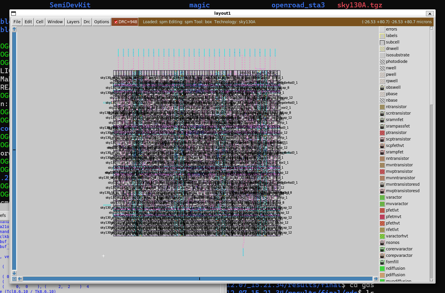
2️⃣ 📐 SemiDevKit
An implementation-oriented development kit bridging semiconductor device theory and practical design workflows:
- Poisson / Drift–Diffusion solvers
- BSIM4 compact device modeling
- SPICE simulation
- NBTI / HCI reliability analysis
- Physical layout using OpenLane-Lite
👉 Transforming physical device understanding into executable design flows.
■ Device Modeling Example (Short Channel Effect)
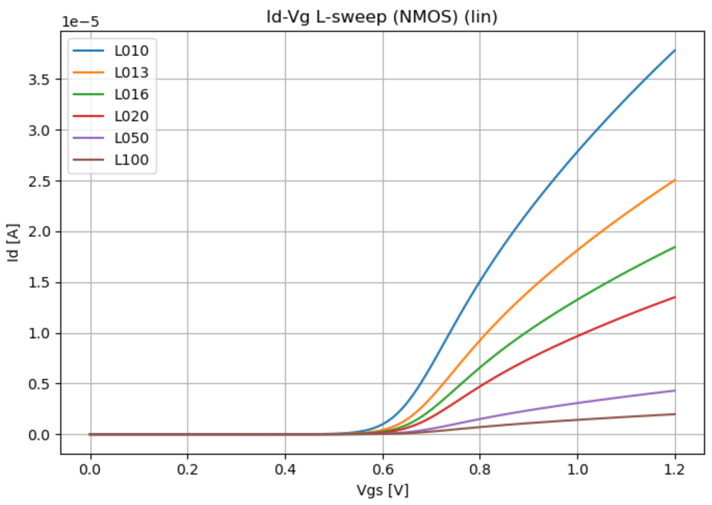
NMOS Vg–Id characteristics (Linear region) modeled with BSIM4,
showing channel-length (L) dependent behavior.
The increase in drain current and slope variation with reduced L
clearly reflects Short Channel Effects, including
threshold voltage roll-off and mobility degradation.
🧱 openlane2-sram|SRAM Hard Macro Integration (Physical Design Proof)
This project demonstrates a complete RTL → GDS flow using OpenLane2 (v2)
by integrating an SRAM hard macro into a macro-aware physical design.
The focus is not SRAM design itself, but realistic hard-macro integration
within an OpenLane2-based physical implementation flow.
- SRAM is treated as an external hard macro (blackbox / LEF / GDS)
- Macro-aware floorplanning with FIXED placement and halo / keepout
- Final GDS generation using the OpenLane2 Classic flow
- Explicitly follows standard SoC practice:
SRAM internals are not exposed or inspected
🔎 Layout Evidence (GDS)
Figure 1: SRAM Macro Block-Level View
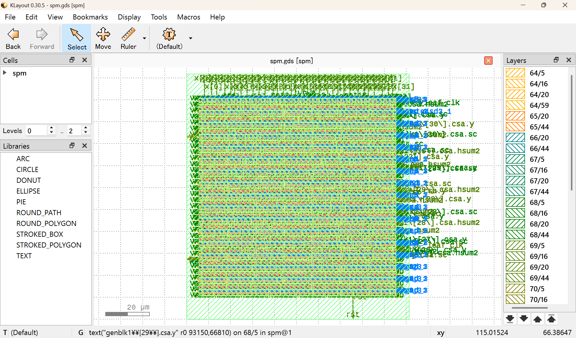
Figure 2: Standard-Cell-Level View Around the SRAM Macro
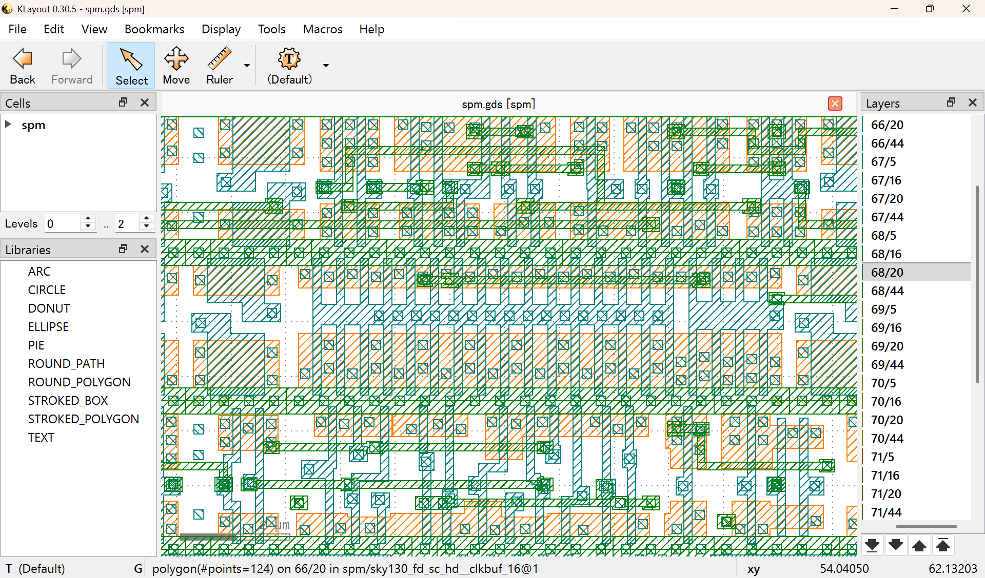
Note:
The SRAM is integrated as a fixed hard macro using abstract views (LEF/GDS).
Its internal transistor-level layout is intentionally not visible, which is consistent with standard SoC physical design practice.
3️⃣ 📘 Edusemi-Plus
Extended materials connecting semiconductor fundamentals with surrounding domains:
- Advanced materials (SiC, GaN)
- Manufacturing equipment and fabs
- Packaging and system integration
- Supply chains and industrial structures
🕰 Legacy Technology (Failure & Recovery Archive)
Legacy Technology is not a retrospective of obsolete processes.
It is a collection of causal case studies documenting how physical mechanisms,
process integration, and usage conditions directly shaped failures,
yield recovery, and business decisions.
- Failures are treated as exposed design constraints, not accidents
- Recoveries are bounded optimizations under real limitations, not ideal solutions
- Many of these structures reappear in modern SoC, AI accelerators, and advanced nodes
These materials explain why AI and control architectures
cannot ignore physical reality,
based on real-world chains of manufacturing, testing,
and market decision-making.
▶ Representative Cases
-
0.25µm DRAM (1998)
Process integration, leakage-dominated retention,
Pause / Disturb failures, fail-stop binning strategy
→ Yield recovery and structural limits revealed
🔗 Open DRAM 0.25µm Case -
PSRAM (Pseudo-SRAM, 2001)
DRAM-derived architecture operated under mobile conditions (90 °C)
→ Technical recovery followed by strategic termination
🔗 Open PSRAM Case
🔐 Note on Confidentiality
This archive is based exclusively on semiconductor technologies
developed more than 20 years ago.It contains no proprietary process recipes, design rules, or operational know-how applicable to current manufacturing.
The focus is on structural failure-and-decision patterns, not secrets.
🎛 Control & Supervisory Architecture
A control architecture that fixes real-time control to PID as the core, while separating design responsibilities through FSM-based supervision and non-real-time intelligence.
4️⃣ 📘 EduController
An educational resource focused on control fundamentals:
- PID control principles
- FSM-based supervisory logic
- Control-oriented design thinking
- Optional HDL template generation
▶ Control Playground (Time Response Demo)
This demo visualizes the time response of a fixed-gain PID controller under colored, adversarial disturbances.
- No sliders
- No tuning
- Only y(t), setpoint(t), and disturbance(t) are shown
Control performance is not explained by words.
The waveform tells the whole story.
5️⃣ 🎛 AITL-Controller-A-Type
A minimal experimental controller implemented in Python to explore a strict separation of responsibilities in control system design:
- Control execution (PID)
- Supervision and decision logic (FSM)
- Limited real-time adaptive assistance (NN / RL, bounded and optional)
- Redesign and analysis support (LLM, design-time only)
This project is a thinking framework for control architecture design,
not a proposal for a new control algorithm
and not an autonomous control system.
- AITL Controller (A-Type) — Official Architecture & Reliability Specification
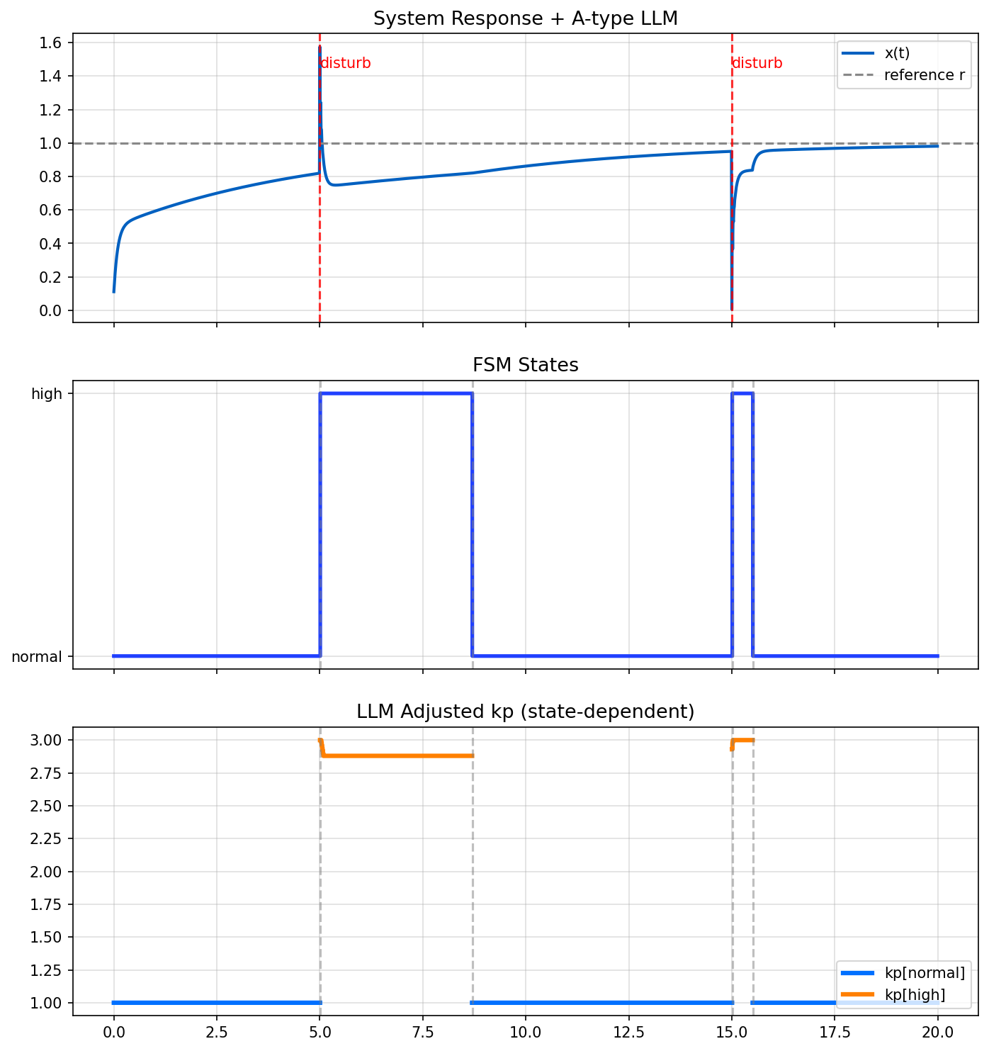
▶ Interactive Verification (Design-Side Playground)
The figure above shows an idealized AITL response,
derived from logged simulation and analysis results.
For hands-on exploration of why this layered separation is necessary,
and where adaptation must stop and design reconsideration begins,
please refer to the interactive playground below.
👉 AITL Control Playground (Interactive)
- Tune PID gains and observe stability, oscillation, and recovery
- Switch FSM modes (TRACK / HOLD / MANUAL)
- Observe when bounded real-time adaptation is insufficient
- See when and why design-time intelligence (LLM-equivalent) would be invoked
This playground is intentionally separated from this PoC page
to preserve the clarity of the minimal AITL structure and responsibility separation.
🧭 Control Architecture Concepts
Core control-architecture concepts that separate runtime operation from design-time recovery.
Both concepts explicitly assume that AI does not replace controllers.
| Concept | Role | Links |
|---|---|---|
| Envelope Control | Runtime enforcement of safe operating envelopes under uncertainty | 🔗 Open | 🔧 Repo |
| Design Recovery Control | Offline recovery of violated control design assumptions | 🔗 Open | 🔧 Repo |
Relationship (non-overlapping):
- Envelope Control constrains how the system operates now.
- Design Recovery Control repairs why the original design no longer works.
These concepts are complementary, not alternatives.
🔔 Ongoing Work: AI Control Safety Package
We are preparing AI Control Safety Package,
a practical design and review package for introducing
AI / LLM-based control systems safely and responsibly.
This is a practice-oriented project derived from
the control architecture concepts presented in this portal.
6️⃣ 🧱 Physical Reference PCB (aitl-physical-reference)
A lowest-level physical reference PCB that anchors abstract control and logic
into real voltage, real current, and real copper.
- Grounds abstract logic into measurable V–I behavior
- Minimal physical system composed only of LED / R / SW / TP
- Physical foundation underlying control, AI, FSM, and PID layers
👉 A reference point showing how physics exists before control.
Logic → Physics → Copper
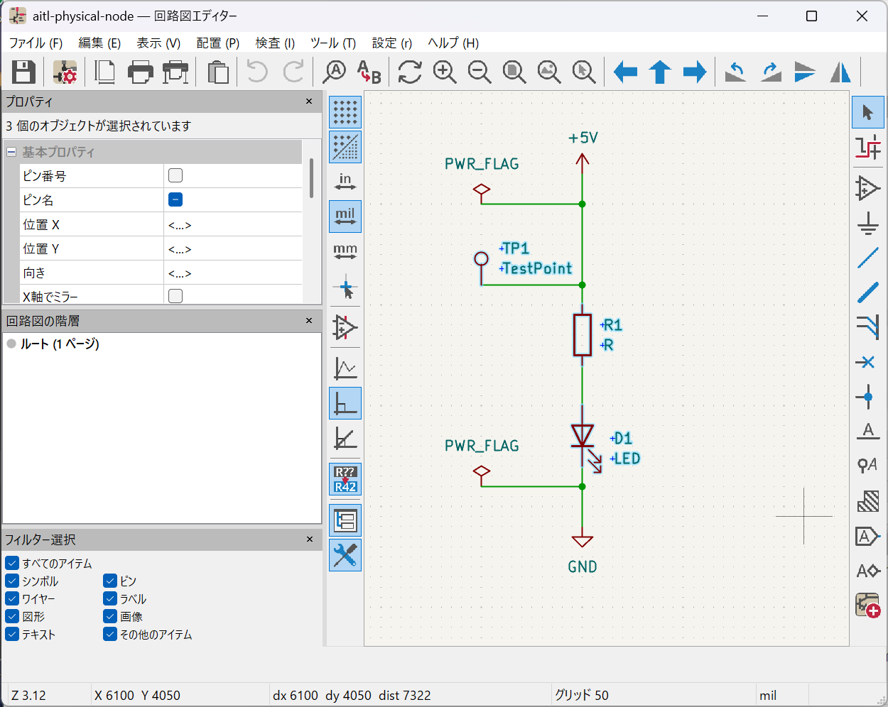
Normative schematic that defines the logical–physical boundary,
fixing abstract logic into measurable voltage and current.
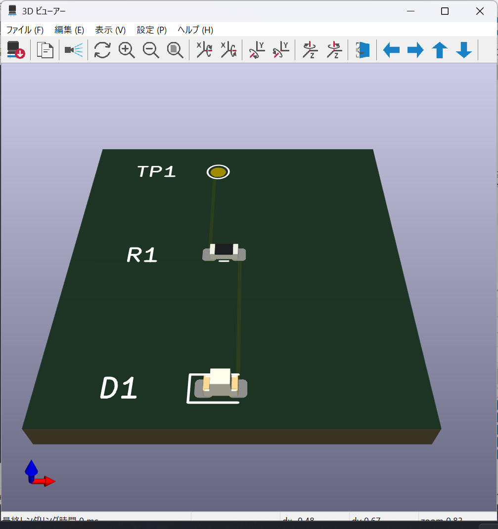
Embodied v1 physical reference board showing real components,
real copper, and explicit physical boundaries.
7️⃣ 🧩 V–I Control ASIC on SKY130
A hands-on educational control ASIC demonstrating a complete flow from
control theory to silicon using PID + FSM.
- Deterministic digital V–I control
- Fixed-point PID with explicit saturation
- FSM-based safety supervision
- Full RTL → GDS flow on OpenLane + SKY130
Logic-to-Physical Consistency (OpenLane v1)
This project demonstrates that the V–I control logic (PID + FSM)
is functionally correct at the RTL level and can be carried through
to physical implementation using OpenLane v1.
By validating the logical behavior first and then mapping it to silicon,
the project clarifies how control theory is concretely realized in an ASIC.
Logical Verification (GTKWave)
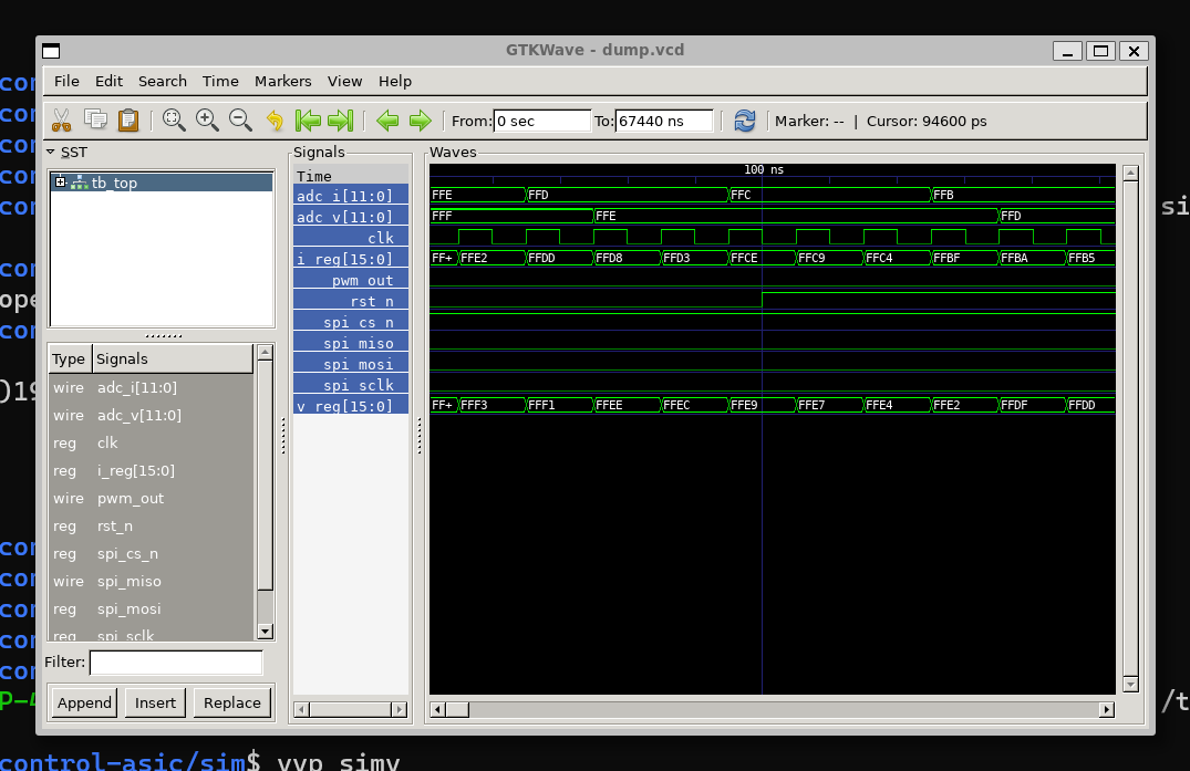
RTL-level functional verification using GTKWave.
The waveform confirms correct PID + FSM behavior at the control interface.
Internal macro implementations are intentionally treated as black boxes.
Physical Implementation (OpenLane v1)
Standard-cell placement and routing snapshot generated by OpenLane v1.
This figure is used for flow inspection, not as a final GDS deliverable.
Note:
This project uses OpenLane v1 as a baseline RTL-to-GDS implementation.
Macro-aware and more advanced physical design examples are provided separately
using OpenLane v2.
⚙️ MEMS / Physical Boundary
A layer that starts from physical models and, through abstraction, control, and design decisions, reaches the MEMS embodiment as the boundary where abstract models cease to be valid.
8️⃣ 📐 mems-ana
Pre-FEM MEMS Structural Exploration Tool
A lightweight analysis tool for early-stage MEMS structural exploration before full FEM simulation.
This tool focuses on capturing dominant deformation modes, scaling trends, and dynamic behavior using simplified analytical and numerical models, enabling rapid design-space exploration without the overhead of full multiphysics solvers.
- Quick evaluation of structural response trends
- Identification of sensitive geometric and material parameters
- Early filtering of infeasible designs before FEM
Demo animation (recommended)
9️⃣ 🖨 Inkjet Technology
A collection of technologies that organize
physical behavior, actuation, and droplet ejection in inkjet systems
as causal structures required for design decision-making.
9-1. 💧 Inkjet Printing — Design Trade-off Models
Minimal physical models that visualize fundamental trade-offs in inkjet printing systems, such as:
- Print quality
- Throughput
- Droplet behavior
These models are implemented as simple Python simulations, intentionally avoiding excessive detail in order to make causal relationships and trade-off structures explicit.
This project serves as a domain-specific example of how physical constraints shape system-level design choices.
9-2. ⚡ inkjet-timing
A design and educational demo that visualizes time-domain causality across electrical, mechanical, and fluid domains in a piezoelectric inkjet system.
By explicitly aligning drive waveforms, structural response, and droplet dynamics along a common time axis, this tool highlights what happens when — and why in coupled multiphysics systems.
- Time-resolved causal relationships
- Clear separation of controllable vs. uncontrollable dynamics
- Educational insight into waveform-driven inkjet behavior
9-3. 🧱 Inkjet Driver IC — Physical Interface Abstraction
A design node that defines the physical boundary where an inkjet driver IC interfaces with the MEMS / fluid domain,
explicitly including PDK and process-level constraints.
This project is based on the GF180 PDK, where
high-voltage (HV) MOS devices required for inkjet driving are manually designed at the layout level.
(This is fundamentally different from sky130-style designs based on standard cells and automatic synthesis.)
What this node defines
- Equivalent loads (V–I–t conditions) passed from MEMS / fluid models to the IC
- Translation of those conditions into IC-side voltage, current, and reliability constraints
- One-to-one mapping between abstract models and physical layouts
(HVMOS / DNWELL / routing / pads) - A clear definition of what is beyond the control of the IC
👉 A design interface that defines the responsibility boundary between physical models and IC design.
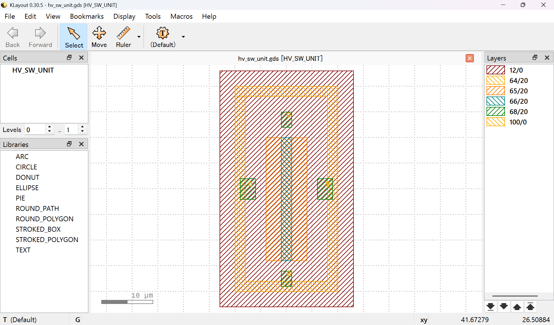
HVMOS Layout as a Physical Interface
The following figure shows a representative high-voltage MOS (HVMOS) layout that serves as the physical interface between the inkjet driver IC and the MEMS / fluid domain.
Rather than a single device in isolation, this example represents the minimum structure actually exposed by the IC: the HV_SW_UNIT, consisting of the HVMOS device, DNWELL isolation, and a continuous guard ring.
This layout visually defines:
- The physical structures for which the IC is responsible
- The starting point of voltage, current, and timing constraints presented to the MEMS / fluid system
- The boundary beyond which behavior is no longer controllable by the IC
🔟 🛠️ Full Code Mechanical Design
A methodology for defining mechanical and MEMS structures as executable code rather than GUI-based CAD operations.
In this approach, CAD is treated not as an authoring tool, but as an execution engine for physical structure and design intent.
- Geometry is generated entirely by Python code
- Dimensions and placements explicitly encode design intent
- Assemblies are defined by placement, not constraint solvers
- CAD files (FCStd / STEP) are treated as byproducts, not primary assets
This methodology enables mechanical and MEMS structures to be reproducible, reviewable, and automatable, and allows them to serve as explicit physical boundary definitions for higher-level control and AITL architectures.
👉 Full Code Mechanical Design provides the physical-structure definition layer upon which Samizo-AITL builds its control and intelligence architectures.
📐 Advanced Geometry Examples (Executable Design Intent)
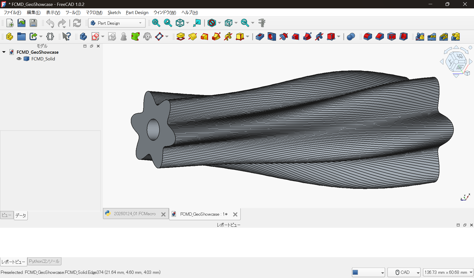
This example shows a twisted loft solid generated purely by Python code,
without any GUI-based CAD operations.
- Cross-sections, placement, and twist angles are explicitly defined in code
- FreeCAD is used not as a drawing tool, but as a geometry generation engine
- The shape is fully reproducible by re-executing the code, preserving design intent
This represents a core concept of Full Code Mechanical Design:
treating executable design code—not CAD files—as the primary design asset.
🎞 AITL Animation Demos
A collection of animation demos that visualize AITL control architectures and
physical, device-level, and multiphysics behaviors over time.
- PID control time responses and control flow
- Role separation across AITL layers (PID / FSM / NN·RL / LLM)
- Time- and space-domain dynamics in inkjet, MEMS, and device physics
These demos are intended to provide a visual understanding of system structure and behavior
prior to engaging with equations or code.
🎞 AITL Control Flow Demo
This demo illustrates how the AITL control architecture operates along the time axis,
where PID × FSM form the real-time control core,
NN / RL provide bounded real-time assistance,
and LLM is isolated as a non-real-time design-support layer.
🔁 Layer roles (summary)
-
PID (real-time control)
Responsible for real-time control execution.
Under nominal conditions, reference tracking is achieved by PID alone. -
FSM (supervisory control)
Monitors system state and detects degradation.
Manages mode transitions
(monitoring / disturbance / recovery / stable)
and determines whether adaptive assistance or redesign is permitted. -
NN / RL (bounded adaptive assist)
Activated only when explicitly permitted by FSM.
Operates as a limited, bounded assist and does not replace PID control. -
LLM (design-time support)
Invoked by FSM only in non-real-time contexts.
Analyzes logs and reliability indicators to support
design-level updates (e.g., PID gains or control policies).
📉 Demo sequence
- Normal operation: PID tracking, FSM monitoring
- Disturbance: error growth detected by FSM
- Conditional adaptation: FSM permits bounded NN / RL assistance
- Design review (if required): FSM invokes LLM
- Recovery: PID re-establishes tracking, FSM returns to stable
Note:
In this demo, the disturbance is recoverable within the scope of PID + FSM supervision.
Therefore, NN / RL and LLM are not activated.
This intentional non-activation itself demonstrates the clear separation of responsibilities in the AITL architecture.
🎯 What this demo demonstrates
This demo confirms that, in AITL:
- Real-time control responsibility remains with PID
- Adaptive intelligence is strictly bounded and conditional
- Design-level reasoning is separated from real-time loops
The architecture preserves control stability and accountability
through explicit responsibility separation.
🎓 AITL Training & Competence Framework (Education & Training)
This framework provides an independent set of documentation for
systematic education, training, and competence verification
based on the Samizo-AITL design philosophy and technical architecture.
It is designed with ISO 9001 Clause 7.2 (Competence) in mind and
formalizes AITL’s responsibility separation
(PID / FSM / NN·RL / LLM) from the perspective of
education, training, and competence management.
👉 AITL Training GitHub Page and Repository
- This framework does not include technical implementations
- It defines training policy, training plans, verification, and records
- The main Samizo-AITL repositories remain the Single Source of Truth
👤 Author
Shinichi Samizo
Independent Semiconductor Researcher
- GitHub: https://github.com/Samizo-AITL
- Zenn: https://zenn.dev/samizo_aitl
- Qiita: https://qiita.com/ctr_bug
- Career Summary: https://samizo-aitl.github.io/about/career-summary/en/
🔐 License & Terms of Use (Hybrid Model)
This portal adopts a hybrid licensing model.
| 📌 Item | License | Description |
|---|---|---|
| 💻 Source Code | MIT License | Free to use, modify, and redistribute |
| 📄 Text Materials | CC BY 4.0 or CC BY-SA 4.0 | Attribution required; share-alike applies for BY-SA |
| 📊 Figures & Diagrams | CC BY-NC 4.0 | Non-commercial use only |
| 🔗 External References | Follow the original license | Cite the original source properly |
⚠️ Important Note on AITL Architecture and Methodology
The licenses above apply to individual materials
(source code, text materials, figures, and diagrams) respectively.
The AITL architecture and methodology as an integrated system
(FSM × PID × LLM layered control design and its associated educational framework)
are not granted by the above licenses.
🚫 Systematic reuse, redistribution, or commercial application
of the AITL methodology or its complete educational structure
requires explicit permission from the project authors.
💬 Technical Discussion / Consultation
This portal does not provide private contact channels
(e-mail, social media, or direct messages).All technical questions, discussions, and consultation inquiries
are handled publicly via GitHub Discussions,
with an emphasis on reproducibility and design context.