aitl-physical-reference
🖼 Image Index — aitl-physical-reference
This page is the canonical, page-rendered figure index for
aitl-physical-reference, covering v0 to v2.
All figures are embedded using absolute GitHub Pages URLs,
so they render correctly at:
👉 https://samizo-aitl.github.io/aitl-physical-reference/docs/img/
🟢 v0 — Minimal Physical Reference
Fig.01 — v0 Schematic
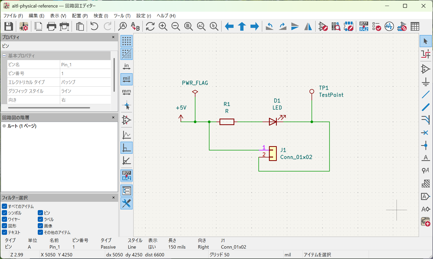
Minimal schematic fixing abstract logic into measurable voltage and current.
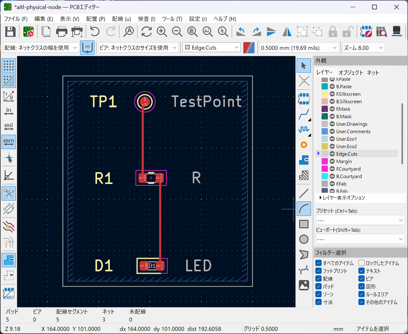
Fig.02 — v0 PCB
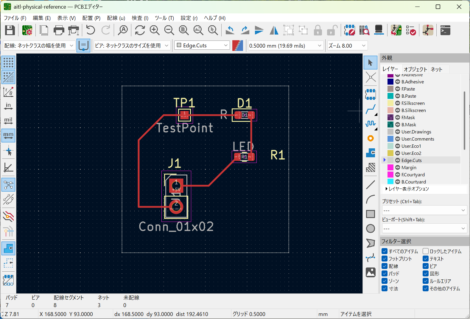
Minimal PCB layout exposing copper routing as a physical constraint.
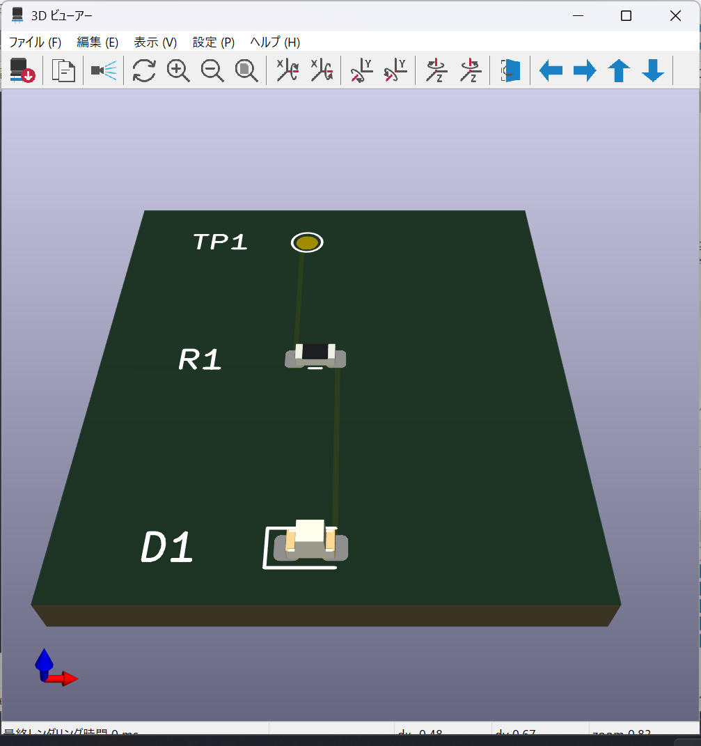
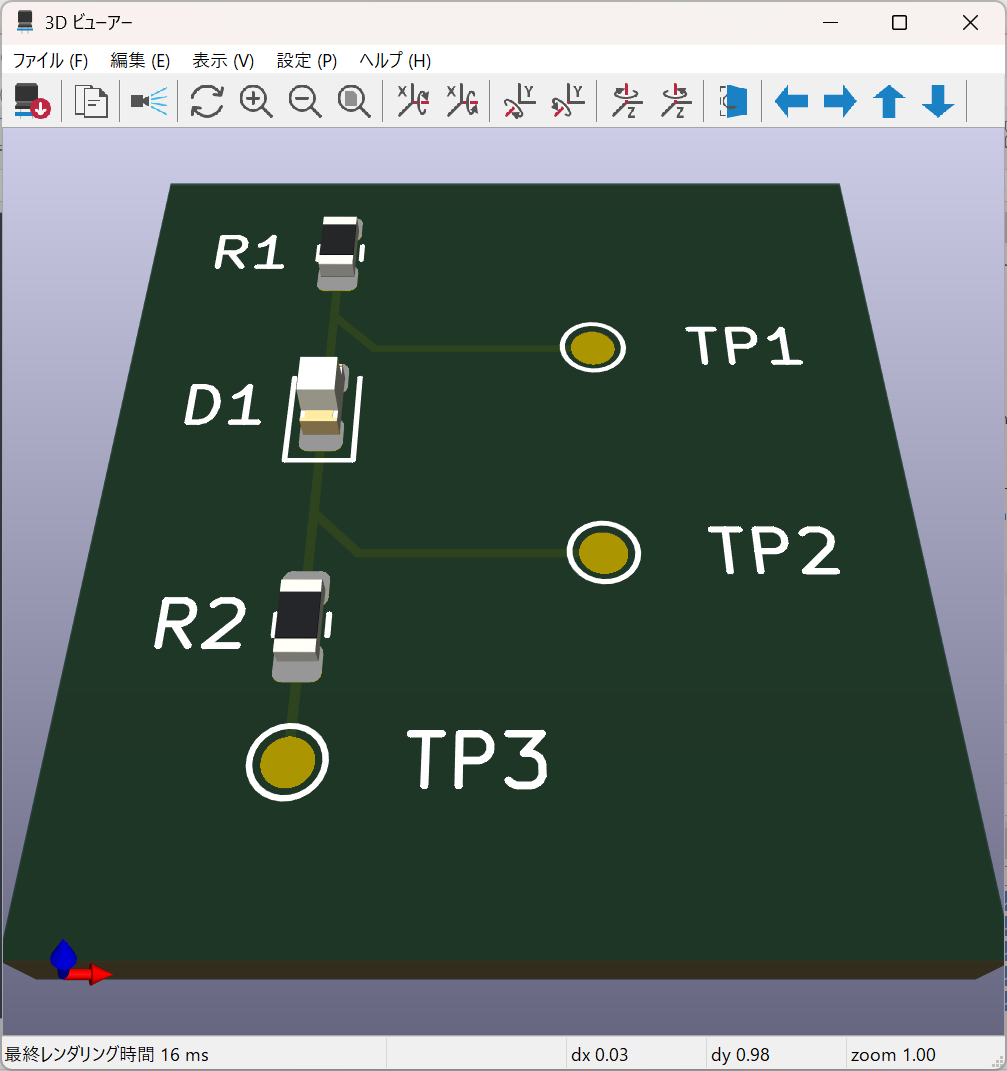
Fig.03 — v0 3D
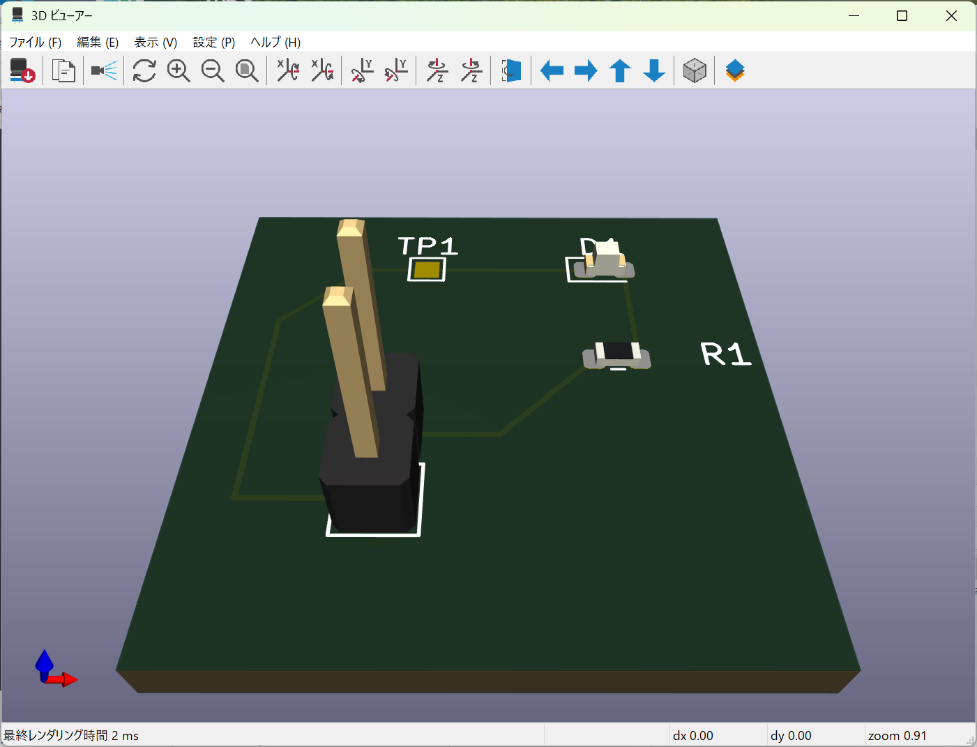
Embodied reality of the minimal physical reference board.
🔵 v1 — Physical ↔ Logical Boundary Reference
Fig.04 — v1 Schematic
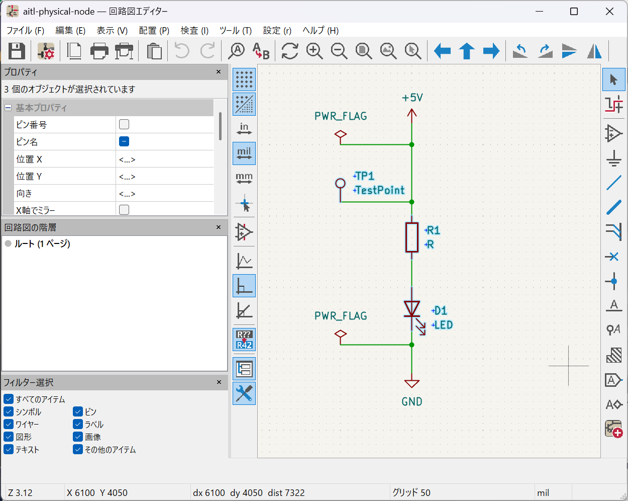
Logical–physical boundary schematic with explicit observability.
Fig.05 — v1 PCB
Boundary-focused PCB layout defining physical constraints.
Fig.06 — v1 3D
Physical embodiment of the logical–physical boundary.
🟣 v2 — Executable Physical Loop Reference
Fig.07 — v2 Schematic
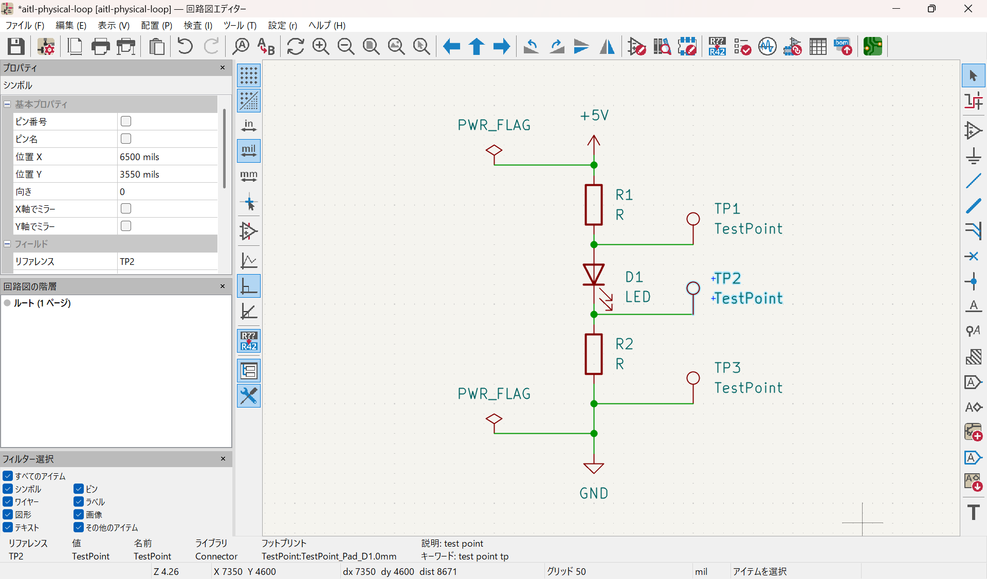
Closed physical loop schematic with no control logic inserted.
Fig.08 — v2 PCB (DRC Clean)
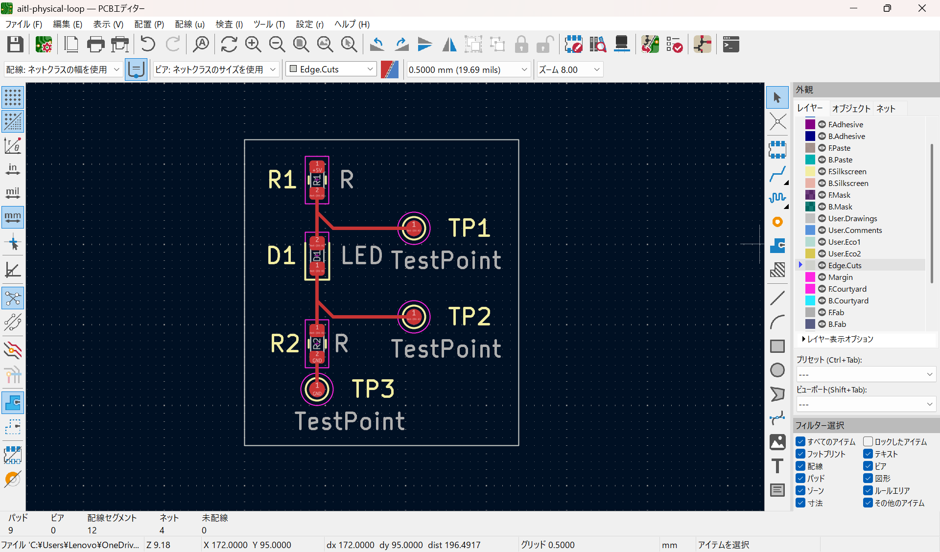
Manufacturable PCB with explicit Edge.Cuts and DRC-clean layout.
Fig.09 — v2 3D
Executable physical loop represented as a real, buildable object.
🔴 v3 — Minimal Physical Control Reference
Fig.10 — v3 Schematic (Physical Control Inserted)
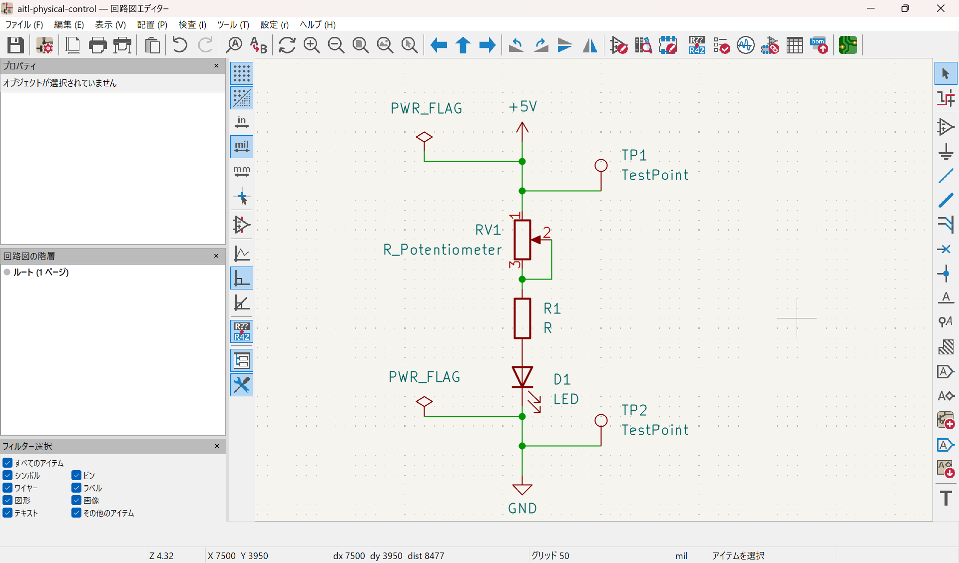
Minimal continuous control element (potentiometer) inserted into the frozen physical loop, without altering loop topology.
Fig.11 — v3 PCB (DRC Clean)
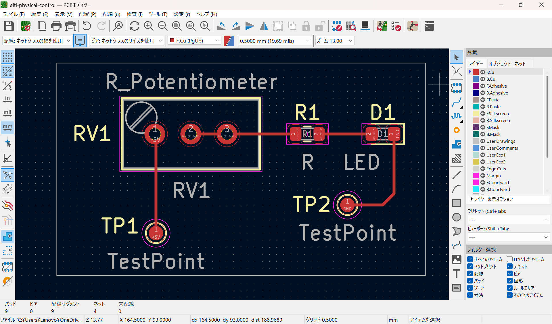
Manufacturable PCB implementing a single closed V–I loop with explicit +5V / GND observation points.
Fig.12 — v3 3D
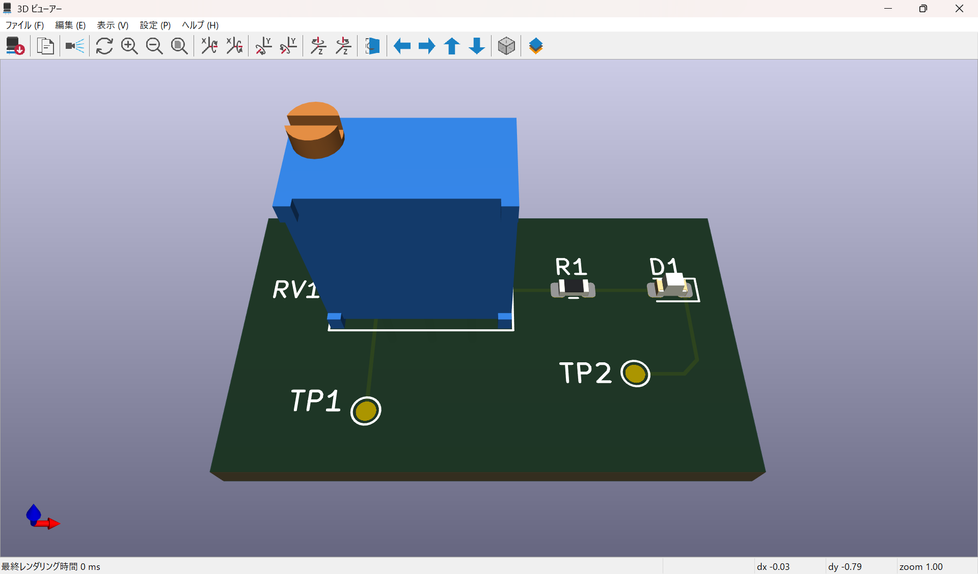
Embodied physical control reference showing the controllable element as a real, buildable object.
📌 Rules (Normative)
- Figure numbering (Fig.XX) is normative and stable.
- Filenames MUST NOT be changed after release.
- All documentation MUST reference figures using Fig.XX.
Example:
See Fig.08 (v2 PCB) for the authoritative physical loop topology.
🔗 Role of This Page
This page is the single source of truth for all visual references
used in discussions, documentation, and architectural reasoning.
No figures should be cited without appearing here.